Another circuit arrived:
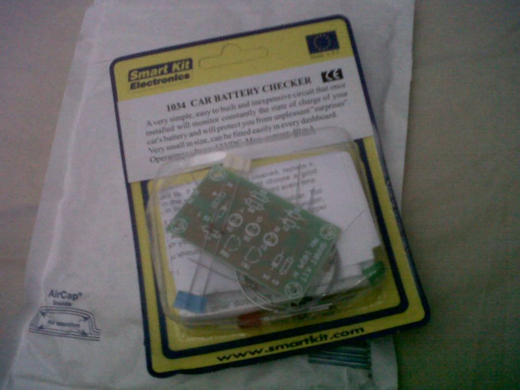
For £6 it cant do any harm to have some built in way of testing the charge in the battery.
cough although i seem to see my battery already has a small window on it for checking the charge cough.
And then came the best bit, building it:
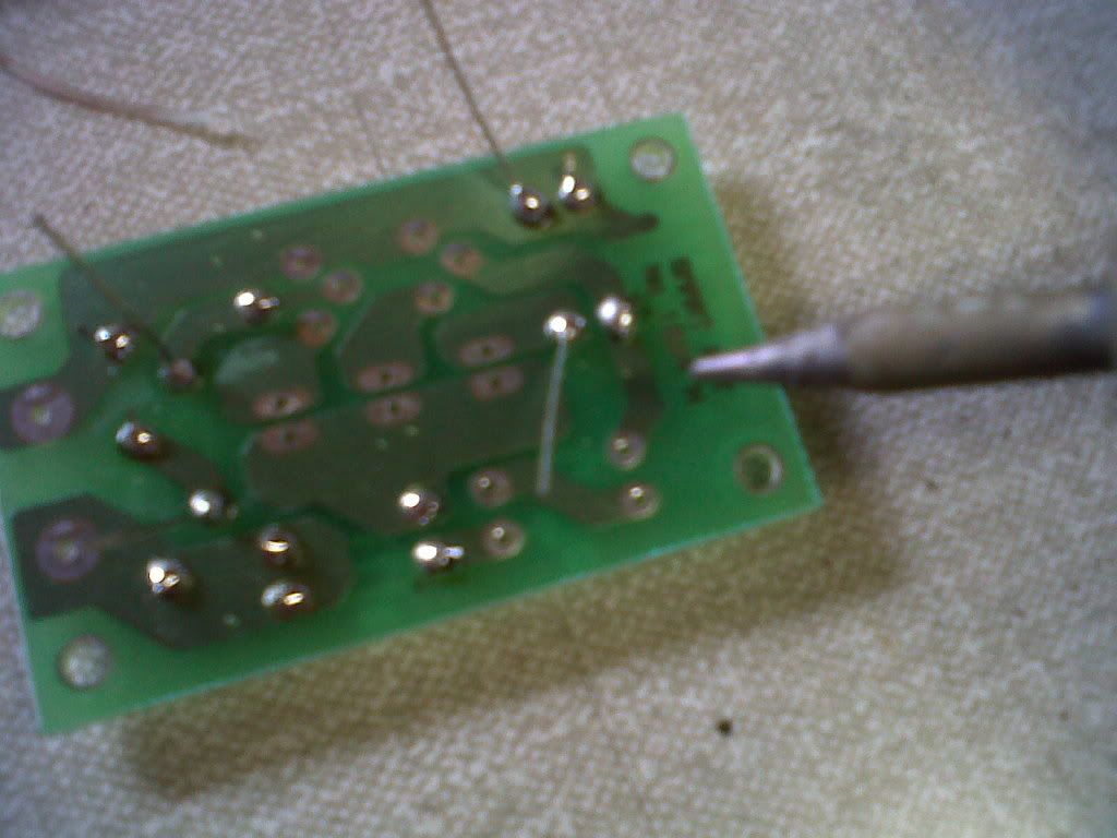
a not so nice thing about building it:

although after all the solder burns ive got, i just dont feel them anymore, the worst burn i got was when i accidentally picked up the soldering iron instead of the solder sucker, now that is sore, had a bandage wrapped on the hand for about a week.
then the leds had to be mounted on fly cables, because where i would be using it it didnt suit to have them mounted directly to the board. So heres a mini guide on soldering fly leads to an led:
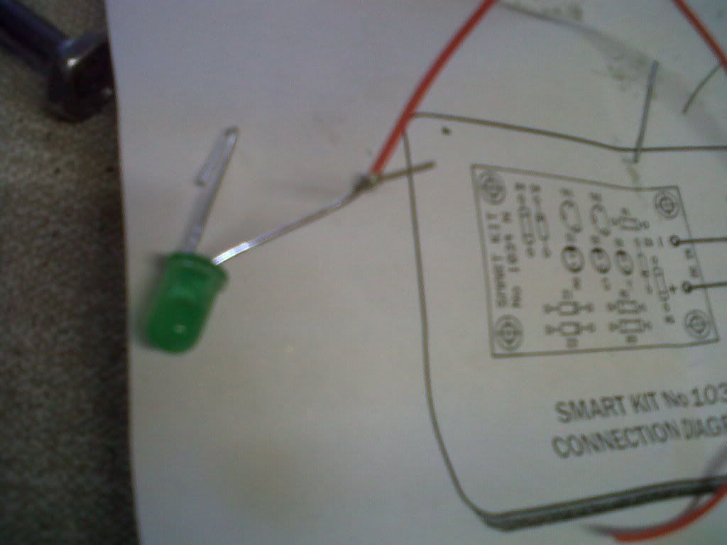
Curl the two legs of the led:
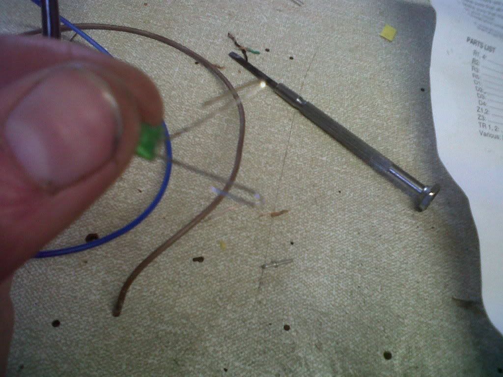
Wrap the wire round the end of the curl, then close the curl down over this bit of wrapped wire so there is now a small look in the led leg, and a bit of wire connected:
Apply some solder to this connection:
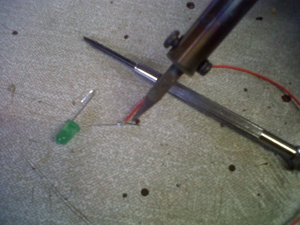
you may find it handy to use something to hold the wire down, such as the screwdriver there, it makes it easier to solder.
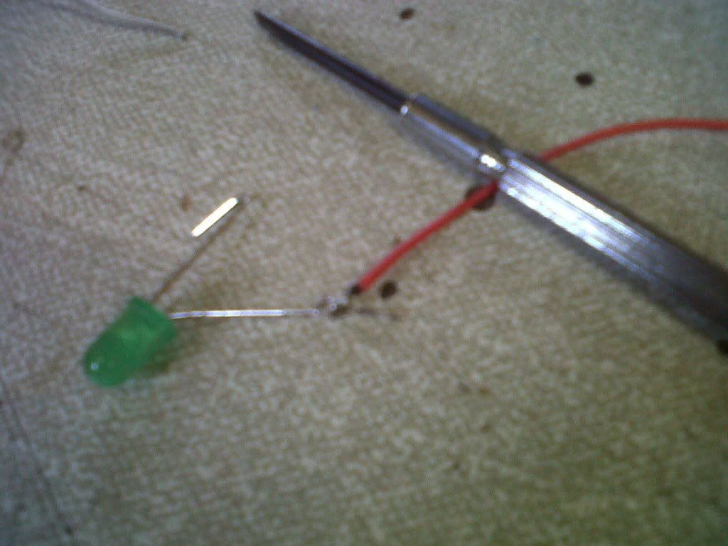
do the same with the other wire. on an led the negative leg is always on the same side as the flat end, also the shorter leg, but if someones already trimmed the legs look for the flat edge.
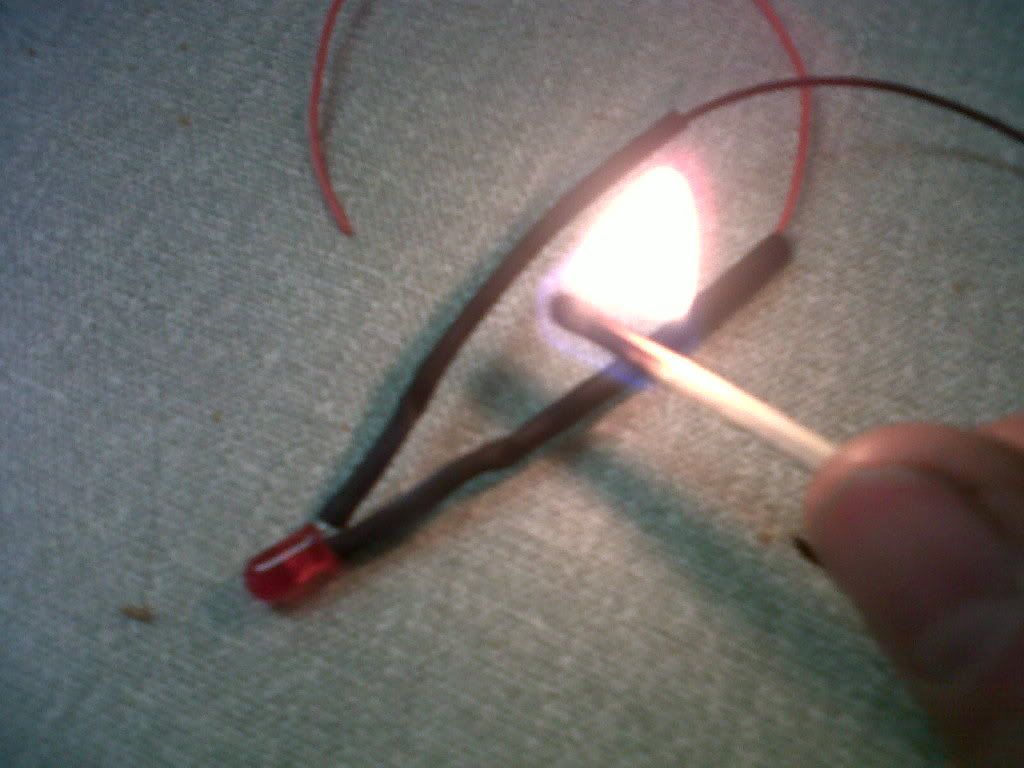
so get the other wire onto the led, and put on some heat shrink tubing for insulation. If you dont have a heatgun, i find a match has enough heat to shrink it:
The 3 leds wired onto the circuit:
i like to wrap the wires round so they are kept tidy, it just involves putting a long length of wire into a vice grip, the other end in a drill chuck and turning it, then you have a long strand of dual core wire, ready for use on something like this.
Getting some glue in round these fly lead connections, because otherwise they can break off very easilly as they are weak wires and only held on by the solder:
Just checking the circuit works, on the battery for my jeep, its about half charged so the yellow lights on:
its not mounted into the car yet, but i do have a very good place for it, just the led holders i ordered came incorrectly, i got too big a size for my leds so im waiting on the correct ones coming. As for the switch used to test the battery its a momentary SPST switch:
it will need a 12mm hole drilled out.
Thats it built, ill show how its actually installed when i get the LED holders, but all it needs is a 12v supply so it can test a battery, i dont know exactly how it knows what LED to put on but it does it without any PIC chip just, 4 diodes, 4 resistors, and 2 transistors do the deciding.