
The Car (and jeep)
-
steve_earwig

- Moderator
- Posts: 19813
- Joined: Thu Oct 04, 2007 6:09 pm
- Location: Jastrebarsko, Croatia http://www.jastrebarsko.hr/lokacija/
Re: The Car
Sorry dude, the last time I knew that was for my RAE almost 30 years ago... There's always Google. Ah
Unskilled meddling sin©e 2007
The submitted form was invalid. Try submitting again.
The submitted form was invalid. Try submitting again.
-
FarmerPug
- 2.0 HDI 110
- Posts: 9656
- Joined: Tue Jun 01, 2010 5:42 pm
- Location: The Countryside, Northern Ireland
- Contact:
Re: The Car
thanks thats what im after ive been looking at the transistor upside down thanks. It ill take 12v ok because ive just said so, ive tried with a voltage regulator and its lovely for a led but completley useless at starting up a relay
-
FarmerPug
- 2.0 HDI 110
- Posts: 9656
- Joined: Tue Jun 01, 2010 5:42 pm
- Location: The Countryside, Northern Ireland
- Contact:
Re: The Car
well now heres how far i got last night before getting tired:
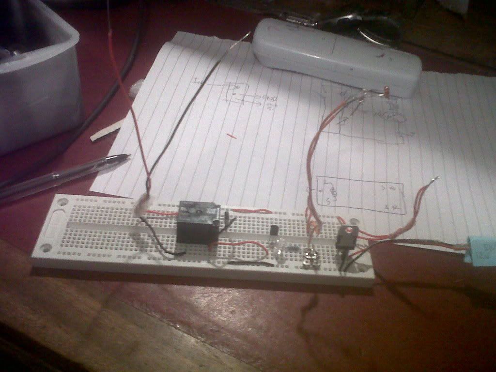
the voltage regulator is coming out it drops the voltage down too much so its not letting the relay fire up, apart from that i have no idea if its working, and it will need the glue gun out once its all going because breadboard isnt normally a permanent measure, just im not at school no more if i was i would have printed a nice and tidy PCB off in a matter of minuites. Is there any commercial PCB makers who do bulk orders of 1.
the voltage regulator is coming out it drops the voltage down too much so its not letting the relay fire up, apart from that i have no idea if its working, and it will need the glue gun out once its all going because breadboard isnt normally a permanent measure, just im not at school no more if i was i would have printed a nice and tidy PCB off in a matter of minuites. Is there any commercial PCB makers who do bulk orders of 1.
-
steve_earwig
- Moderator
- Posts: 19813
- Joined: Thu Oct 04, 2007 6:09 pm
- Location: Jastrebarsko, Croatia http://www.jastrebarsko.hr/lokacija/
Re: The Car
My dad used to make some really neat little circuit boards out of Veroboard. I guess, once you have your circuit running how you want it, you could transfer all the components to one of these.
Lawks, there's even software to help you design them now http://www.marlwifi.org.nz/other/stripboard-magic
Lawks, there's even software to help you design them now
Unskilled meddling sin©e 2007
The submitted form was invalid. Try submitting again.
The submitted form was invalid. Try submitting again.
-
FarmerPug
- 2.0 HDI 110
- Posts: 9656
- Joined: Tue Jun 01, 2010 5:42 pm
- Location: The Countryside, Northern Ireland
- Contact:
Re: The Car
it looks like a good enough idea but vero board hasnt much size advantage over breadboard, anyhow its ok for now ill get a bit of glue to hold it all in. That is of course once its running.
-
FarmerPug
- 2.0 HDI 110
- Posts: 9656
- Joined: Tue Jun 01, 2010 5:42 pm
- Location: The Countryside, Northern Ireland
- Contact:
Re: The Car
Well now the circuit isnt sensitive enough just flicked the relay on as soon as power came through, which is understandable when a single tranisitor only needs 0.7v as a switch on voltage, the solution a darlington pair ie a pair of transistors which raises the turn on voltage to 1.4v which really means better sensitivity for the ldr. But anyhow i typed in darlington pair in google and what do you know a perfectly drawn circuit diagram of what im trying to make, i couldnt seem to download it as an image so heres a screenshot:
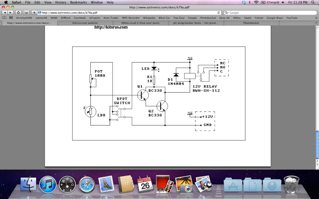
And now im going to try and explain it only from what i know.
Im going to use this circuit with the exception of its DPDT switch because thats there to decide wheather the relay turns on when its dark or when its light just by swapping round the position of the voltage divider (http://en.wikipedia.org/wiki/Potential_divider). The ldrs resistance gets higher in the dark so it stops electricty flowing in the dark, but in a voltage divider if its at the top that means when its dark it stops any electricity getting down into the transistor, the vairable resistor is there to adjust sensitivity if its resistance is low enough it lets the electricity just flow past the transistor as it takes the path of least resistance. Then you can put the LDR at the bottom of a voltage divider so it sends power to the transistor when its dark ie its resistance is high in the dark, and electricity picks the path of least resistance to the transistor. Hope that slightly waffly speech clears that up. Then a transistor is just an electric switch 2 are here so it takes more power to turn them on. Because a relay is used a diode is needed as the colapsing magnetic field of the relay causes back EMF which can damage the transistors and the reverse bias diode (put in the wrong way) dissipates this energy. So thats what ive built on the breadboard, its not fully ready for pictures yet, glue is drying but hopefully it will work.
Due to the fact i ordered 330 ohm resistors and this says 1k ohm resistors i went up into the attic for something electrical and broken:
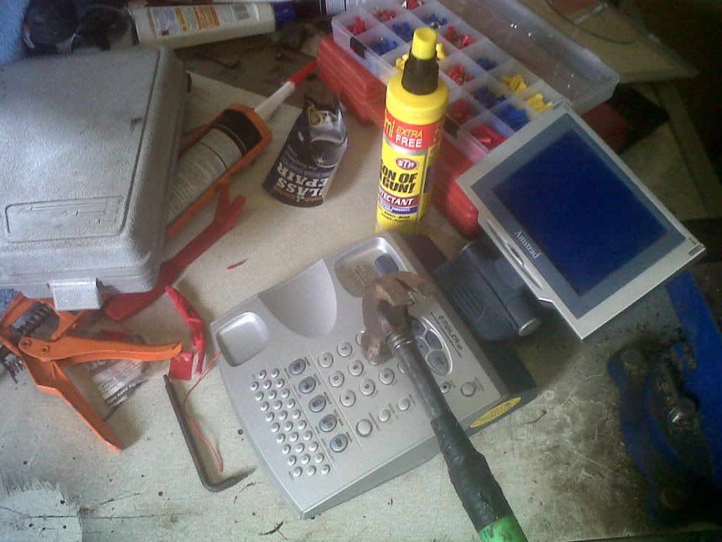
I didnt find any suitable resistors in this while taking it apart but i have learnt one suprising fact about this amstrad phone its build quality and component quality isnt great, suppose thats why its been in the attic for about 5 years, i didnt actually use a hammer to take it apart.
And now im going to try and explain it only from what i know.
Im going to use this circuit with the exception of its DPDT switch because thats there to decide wheather the relay turns on when its dark or when its light just by swapping round the position of the voltage divider (http://en.wikipedia.org/wiki/Potential_divider). The ldrs resistance gets higher in the dark so it stops electricty flowing in the dark, but in a voltage divider if its at the top that means when its dark it stops any electricity getting down into the transistor, the vairable resistor is there to adjust sensitivity if its resistance is low enough it lets the electricity just flow past the transistor as it takes the path of least resistance. Then you can put the LDR at the bottom of a voltage divider so it sends power to the transistor when its dark ie its resistance is high in the dark, and electricity picks the path of least resistance to the transistor. Hope that slightly waffly speech clears that up. Then a transistor is just an electric switch 2 are here so it takes more power to turn them on. Because a relay is used a diode is needed as the colapsing magnetic field of the relay causes back EMF which can damage the transistors and the reverse bias diode (put in the wrong way) dissipates this energy. So thats what ive built on the breadboard, its not fully ready for pictures yet, glue is drying but hopefully it will work.
Due to the fact i ordered 330 ohm resistors and this says 1k ohm resistors i went up into the attic for something electrical and broken:
I didnt find any suitable resistors in this while taking it apart but i have learnt one suprising fact about this amstrad phone its build quality and component quality isnt great, suppose thats why its been in the attic for about 5 years, i didnt actually use a hammer to take it apart.
-
FarmerPug
- 2.0 HDI 110
- Posts: 9656
- Joined: Tue Jun 01, 2010 5:42 pm
- Location: The Countryside, Northern Ireland
- Contact:
Re: The Car
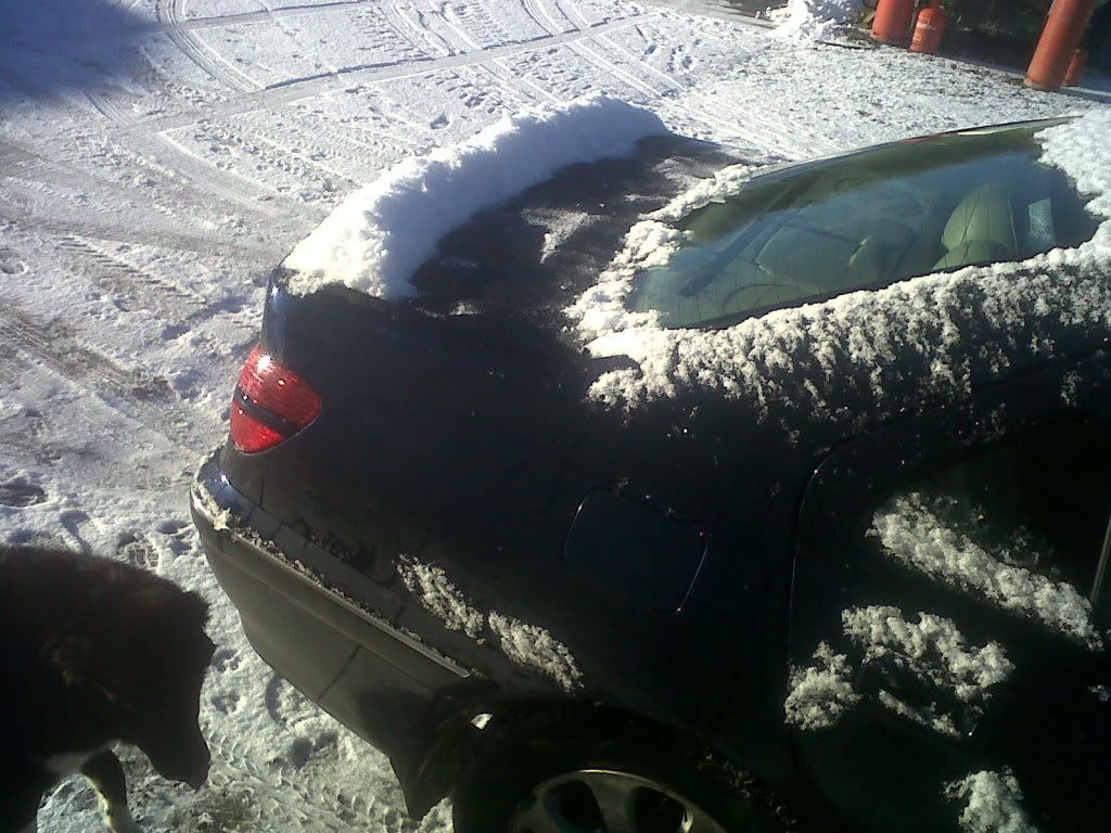
The new spoiler came today, just fell right out of the sky:
-
FarmerPug
- 2.0 HDI 110
- Posts: 9656
- Joined: Tue Jun 01, 2010 5:42 pm
- Location: The Countryside, Northern Ireland
- Contact:
Re: The Car
I got the 12v feed from the battery into the cabin at last the wire, insulation tape, and cable ties for £5 ebay cant beat that.
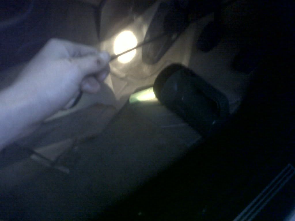
So a big screwdriver had to be pushed into the hole where the wires come through the bulkhead,
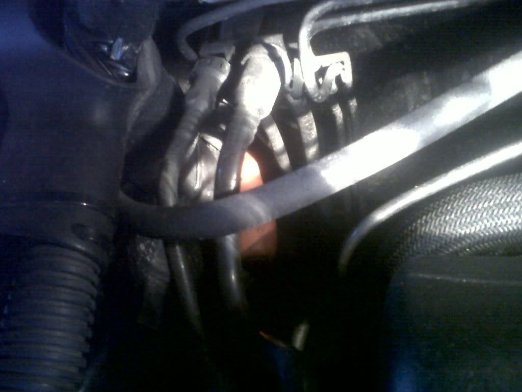
it needs plenty of swivelling about to make the hole big enough for the wire to pass through and even then it takes a very hard push to get it through, once through the hard parts over, just pull the wire out the other side:
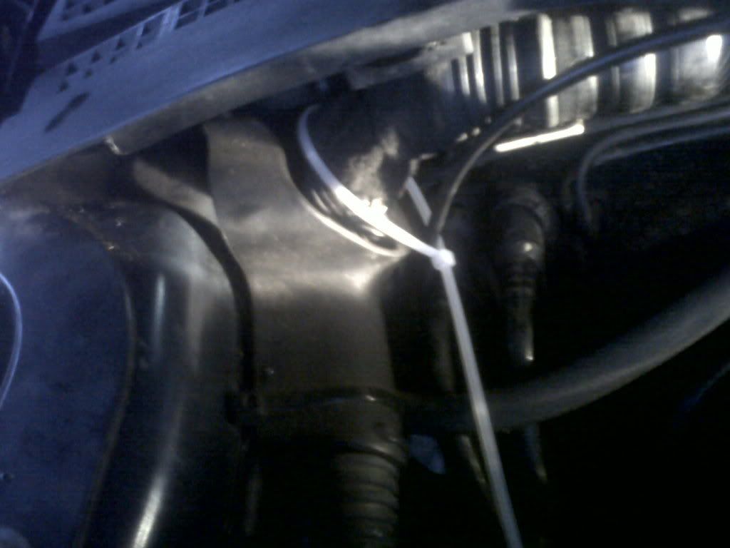
And then its a case of using cable ties to get it over to the battery, i just used the big thick wire on the bulhead to tie them onto:
When i got the wire into the battery box, i put on some hoop ends onto the wires and put them onto the two terminals:
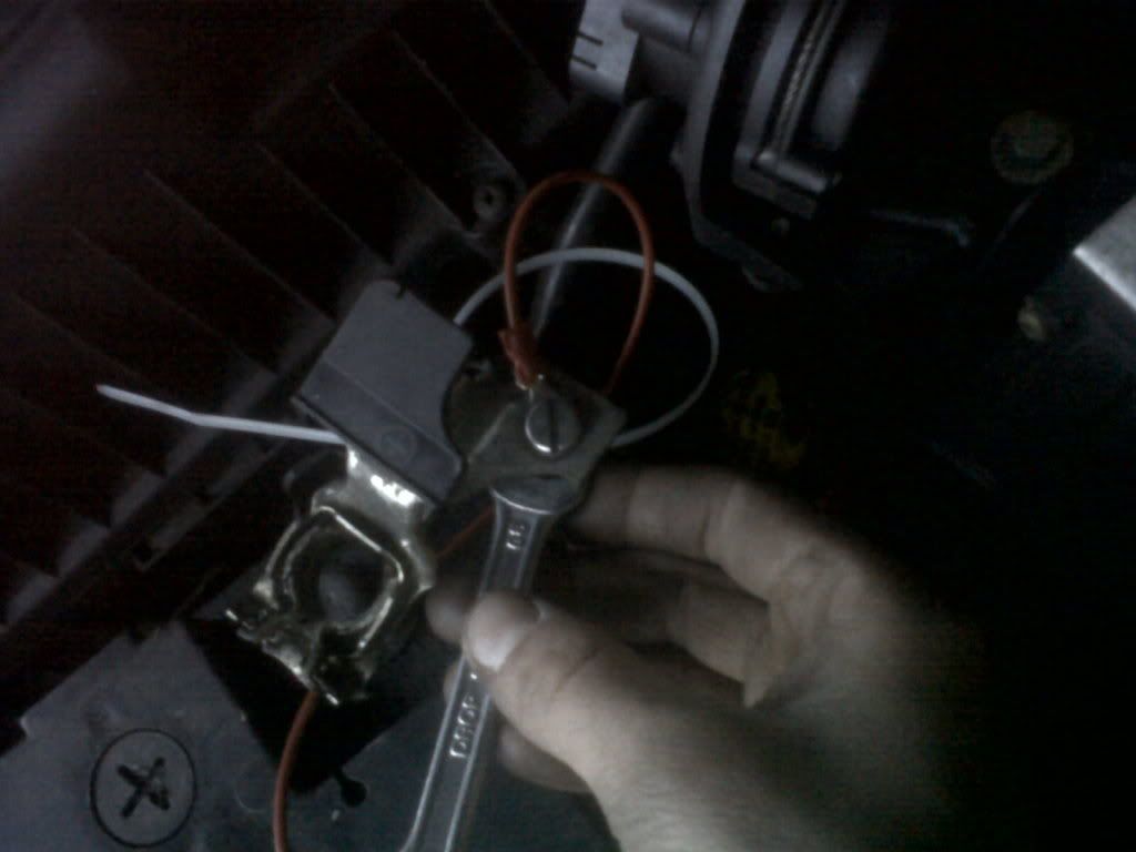
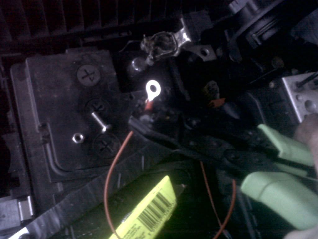
And thats a good 12v feed in the car now. Ill be able to use it for the footwell lights but also anything else that i want to add inside the car without buggering up the BSI
So a big screwdriver had to be pushed into the hole where the wires come through the bulkhead,
it needs plenty of swivelling about to make the hole big enough for the wire to pass through and even then it takes a very hard push to get it through, once through the hard parts over, just pull the wire out the other side:
And then its a case of using cable ties to get it over to the battery, i just used the big thick wire on the bulhead to tie them onto:
When i got the wire into the battery box, i put on some hoop ends onto the wires and put them onto the two terminals:
And thats a good 12v feed in the car now. Ill be able to use it for the footwell lights but also anything else that i want to add inside the car without buggering up the BSI
-
steve_earwig
- Moderator
- Posts: 19813
- Joined: Thu Oct 04, 2007 6:09 pm
- Location: Jastrebarsko, Croatia http://www.jastrebarsko.hr/lokacija/
Re: The Car
I'm going to nick that last post for the knowledge base 
Unskilled meddling sin©e 2007
The submitted form was invalid. Try submitting again.
The submitted form was invalid. Try submitting again.
-
FarmerPug
- 2.0 HDI 110
- Posts: 9656
- Joined: Tue Jun 01, 2010 5:42 pm
- Location: The Countryside, Northern Ireland
- Contact:
Re: The Car
I noticed that, good enough hope it helps the rest of you.
-
steve_earwig
- Moderator
- Posts: 19813
- Joined: Thu Oct 04, 2007 6:09 pm
- Location: Jastrebarsko, Croatia http://www.jastrebarsko.hr/lokacija/
Re: The Car
Cheers for that, it's been asked many times but the one Niz did is text only, and nothing's as good when it don't have pikchers 
Unskilled meddling sin©e 2007
The submitted form was invalid. Try submitting again.
The submitted form was invalid. Try submitting again.
-
FarmerPug
- 2.0 HDI 110
- Posts: 9656
- Joined: Tue Jun 01, 2010 5:42 pm
- Location: The Countryside, Northern Ireland
- Contact:
Re: The Car
well the only hard part is breaking through the grommet in the bulkhead.
as for this electrical project, the breadboard is not working right, its ok for building a circuit on a desk just to check it works but in its application in the car all the wires come loose and it simply doesnt work, so ive ordered some of this vero board 3 for £2, and because im not sure of the transistor pin layout ive bought 4 new ones the metal capped ones with the tab for easier pin location. With the vero board i can solder all the components together which will mean a better contact than simply pushing a wire down a hole and putting hot glue over it. It will work eventually but ill wire up these footwell lights to the 12v line just for a look at them working because ive never seen them working.
Im putting an inline fuse in front of the 2 bulbs what rating should it be.
-
FarmerPug
- 2.0 HDI 110
- Posts: 9656
- Joined: Tue Jun 01, 2010 5:42 pm
- Location: The Countryside, Northern Ireland
- Contact:
Re: The Car
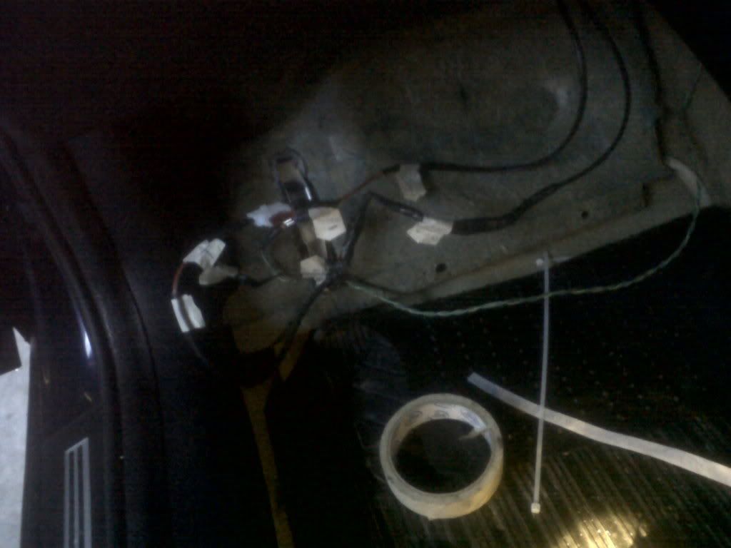
I wired up the footwell lights, my box of tricks isnt ready yet but i couldnt wait i wanted to see the footwells lit up, so i have the footwell lights wired up fused with a switch so heres the wiring all labeled so it wont be hard to add the electric circuit:
And heres the lights working:
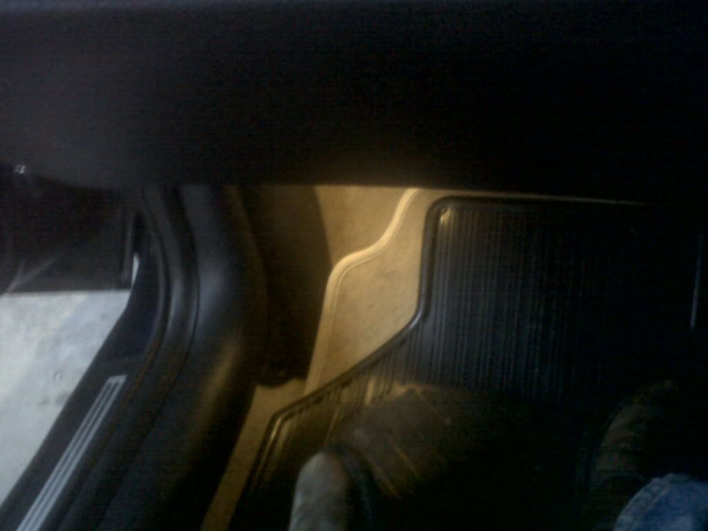
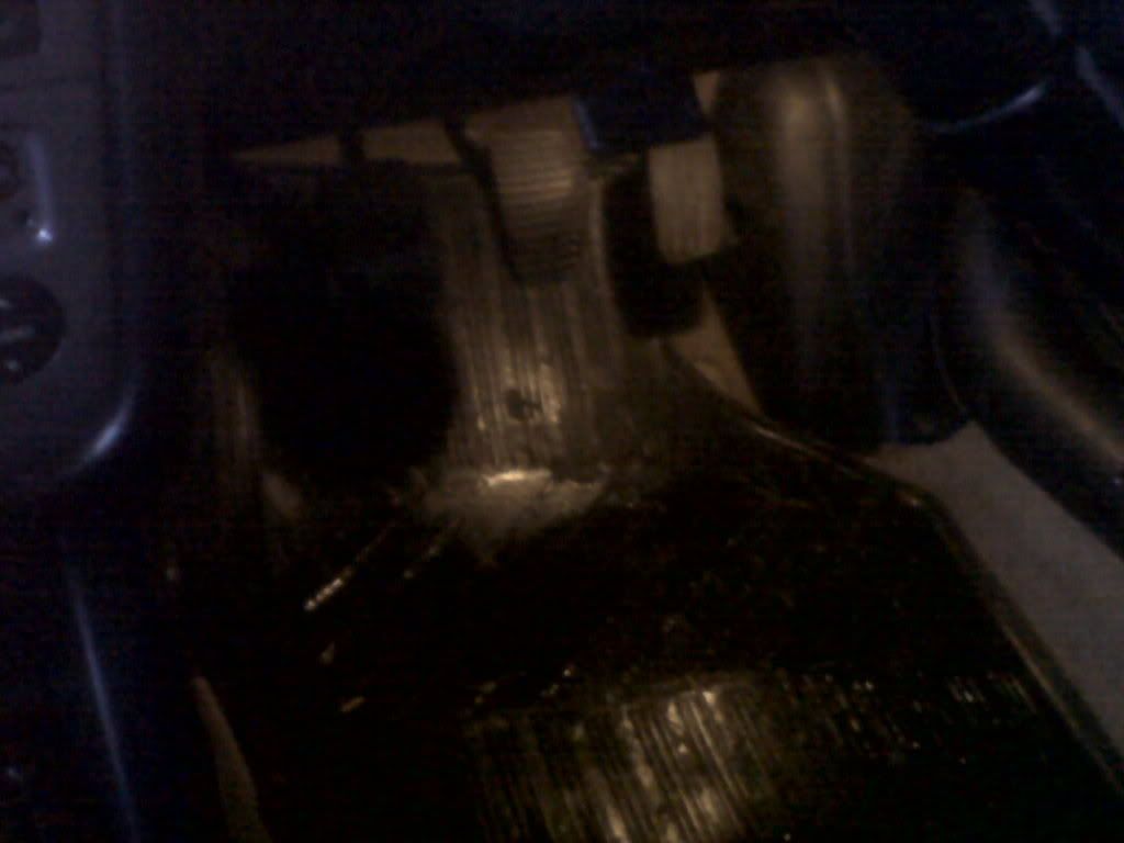
bad light levels on the camera, they are more noticeable at night:
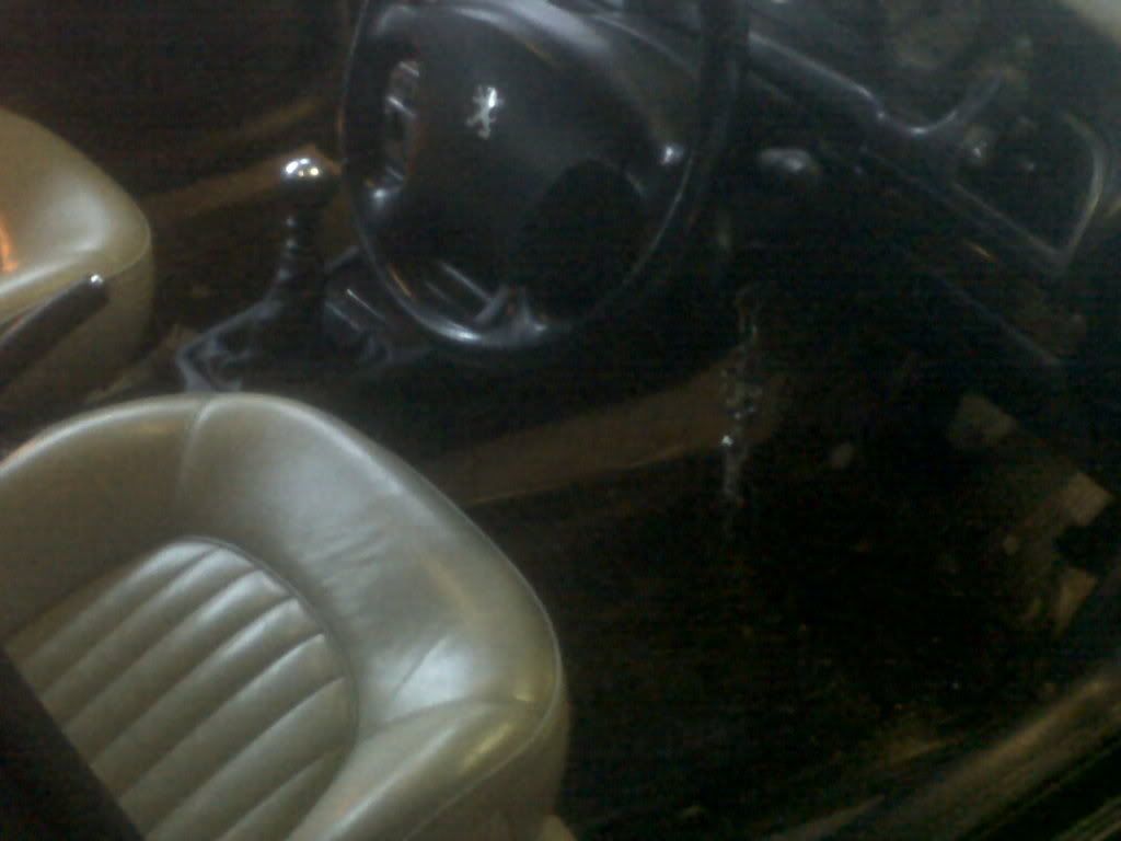
So at the moment the footwell lights work safely without hurting the bsi but they are useless unless they switch on at the same time as the courtesy lights.
And heres the lights working:
bad light levels on the camera, they are more noticeable at night:
So at the moment the footwell lights work safely without hurting the bsi but they are useless unless they switch on at the same time as the courtesy lights.
-
Welly

- The moderator formally known as Welton
- Posts: 15033
- Joined: Tue Jan 10, 2006 12:52 pm
- Location: East Midlandfordshire
Re: The Car
Great stuff, looks like you're getting somewhere now.
Cars in my care:
2021 Kia Spottage 1.6 Pez Turbo Dual Clutch Gearbox Trickery
2013 Renner Twingo - donkey work
2021 Kia Spottage 1.6 Pez Turbo Dual Clutch Gearbox Trickery
2013 Renner Twingo - donkey work
-
FarmerPug
- 2.0 HDI 110
- Posts: 9656
- Joined: Tue Jun 01, 2010 5:42 pm
- Location: The Countryside, Northern Ireland
- Contact:
Re: The Car
One day at a time, i havent used these footwell lights much, they will be nice when they turn on automatically. But i dont really think there is a time when you jump into your car and go i think i need to turn the footwell lights on, unless its dark and you want to polish your shoes, there you go a new selling point a mobile shoe polishing point.