Wiring up Footwell lights
Moderator: Moderators
-
Doggy

- Mod with a 2.2 HDi, De-Fapped!
- Posts: 10710
- Joined: Mon Oct 13, 2008 11:49 pm
- Location: Northants
Re: Wiring up Footwell lights
No, you're concern is wheter the electronics in the RS gubbins are able to handle the voltage range you're car develops, (12 - 15 V or so).
2002 HDi 2.2 Exec Estate, (2008-12) (wonderful)
2003 HDi 2.2 6-speed Exec Estate (2012-19) (also a gem)
2009 Citroen C5 2.0 HDi VTR+ Estate (godawful heap)
2008 BMW E91 330i touring (great fun - murdered by a reversing SUV)
2007 BMW E91 325i touring (slower smoother quieter)
2003 HDi 2.2 6-speed Exec Estate (2012-19) (also a gem)
2009 Citroen C5 2.0 HDi VTR+ Estate (godawful heap)
2008 BMW E91 330i touring (great fun - murdered by a reversing SUV)
2007 BMW E91 325i touring (slower smoother quieter)
-
FarmerPug
- 2.0 HDI 110
- Posts: 9656
- Joined: Tue Jun 01, 2010 5:42 pm
- Location: The Countryside, Northern Ireland
- Contact:
Re: Wiring up Footwell lights
it takes different voltage inputs ok, 3.5v to 50v, are you on about the fact that the voltage coming out of the car fluctuates sometimes its at 10 or sometimes its at 14v, i wouldnt say it would harm the RS yoke because it would only be swithcing on when the door is opened, in that bit of time there cant be too much fluctuation. Im still waiting for them to reply on that but as long as the bsi doesnt blow, at least the RS device can be replaced relativley cheaply compared to the cost of a BSI
-
FarmerPug
- 2.0 HDI 110
- Posts: 9656
- Joined: Tue Jun 01, 2010 5:42 pm
- Location: The Countryside, Northern Ireland
- Contact:
Re: Wiring up Footwell lights
Its an old thread, but hey it can now finally end with a solution.
Get a 12v safe feed from the battery through the bulkhead into the footwell area, put an ldr into the courtesy lights placed so it only picks up the bulb, thread the wire down the a pillar and into the footwell area, and get 2 footwell lights cut into the carpet at the top of the footwells, connect the 2 and have a +ve and -ve ready to supply them with power, also install a spst switch to allow you to turn the whole thing on and off, thread the wires into the footwell area. Now purchase this circuit:
http://www.quasarelectronics.com/3079a- ... switch.htm
buy the already built one (covered by warranty better), snip off the ldr and solder the fly leads into that place, wire it all up accordingly and set it to light activation so the relay is off when the lights are off so your battery isnt draining. Check it works, do some fine adjustments, and use cable ties to tidy all the wires up, put the footwell top carpets back in place and enjoy bsi friendly footwell lights:
B7LTqagatlQ
you even get the delay of the courtesy lights so when you unlock the 406 the footwells will now light up. This system also allows room for expansion, just add more relays for this thing to switch on as it couldnt really cope with a big load, you could wire up footwell lights in the back, or lights in the door handles.
So that seems to be the best solution i can find for wiring up footwell lights in a multiplexed 406.
-
FarmerPug
- 2.0 HDI 110
- Posts: 9656
- Joined: Tue Jun 01, 2010 5:42 pm
- Location: The Countryside, Northern Ireland
- Contact:
Re: Wiring up Footwell lights
after all this learning, ive finally come up with a final draft instructional guide for installing footwell lights correcly, should i add it to this thread or start a new one?
-
FarmerPug
- 2.0 HDI 110
- Posts: 9656
- Joined: Tue Jun 01, 2010 5:42 pm
- Location: The Countryside, Northern Ireland
- Contact:
Re: Wiring up Footwell lights
Footwell Lighting Instalation Guide
Right, now after all the time spent on getting these footwell lights, im very happy that they are now working so now from my experience (ie almost wrecking the BSI, trying 4 different circuits as a solution, and burning my hand a number of times with a soldering iron) i can now make a followable guide on how you can install footwell lights without causing any trouble to your BSI. But this isnt just for D9 multiplex owners, if you D8 owners have a similar thing and want to add footwell lights without drawing power from whatever the equivilant of the BSI is then this is the guide.
So to begin then, do the easy part, buy a pair of them peugeot square courtesy lights off ebay, you know the ones that old 205s had as a courtesy light, they will do best, but i had an old merc one and one from the boot of a 206 it doesnt matter too much what they look like unless your an acrobat and sit with your head in the footwell and legs on the chair, in which case i must say try the other way its comfier, a scrappies is the best place to look and see the best courtesy light for the job..
anyhow get the carpet topping of the footwells out, cut a hole for the lights, and slot the light in, tuck the material in carefully and tightly round the light and use glue just to get it in right and this is what it looks like when finished:
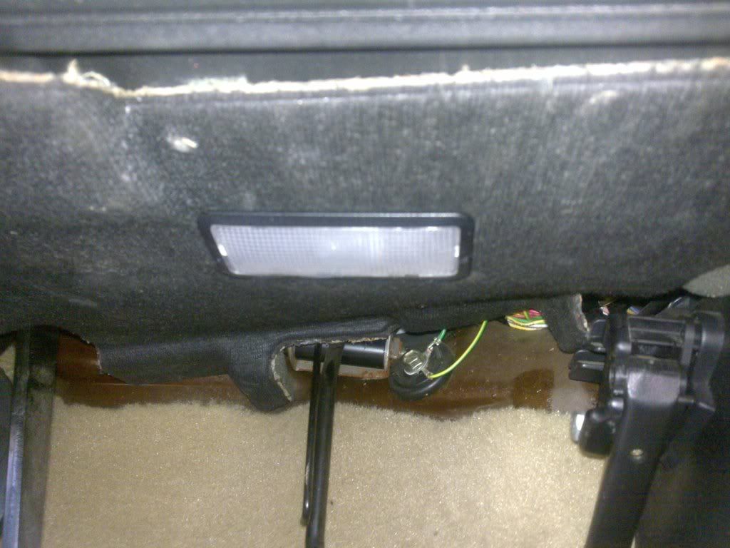
Now each light has 2 wires (as you would expect), because its a bulb there isnt any issue with politary, light will still come out. All the wiring for the footwell lighting gubbins is best done in the passenger side of the car because there is more room (well there is at least in cars with the steering on the right side) you dont want a load of wires under the drivers side as theres enough there already, as well as the pedals and steering. Anyhow you need to connect 2 core (+ve and -ve wire available from any hardware shop in a roll) cable from the drivers side footwell light, to the passenger footwell, this is very easy, it just threads behind the dash (threading doesnt need any of the dash to be pulled apart its easy enough), use plenty of cable ties to clamp the wire tight, and keep rattles away, make sure there is more than plenty of wire over at the passenger side, ie it should be able to reach the door.
With the drivers footwell open its a good time to bring the 12v power supply into the car, the 12v power supply has to come from the battery through the bulkhead into the passenger footwell. Of course some will know of other ways of getting a constant 12v feed, but this way worked, the bulkhead in front of the driver has a big collection of wires coming into the cabin, you can see the big thing below the scuttle, push a screwdriver through this, and twist it about until eventually the wire can go throught, this isnt easy bit it is possible, again get the wire into the passenger footwell, use cable ties and always make sure no wires obstruct the movement of the pedals. Once 12v is available at the passenger footwell you can put the drivers side footwell cover back up.
So you now have 12v into the car, you now need to put 2 wires onto the passenger side light, strip the wire back, for this one and the wire coming from the light at the drivers side footwell, take the 2 brown or red wires (whatever is inside the 2 core stuff) and put the two into the bottom of a terminal block, do the same with the blue/black wire, then on the other side of the terminal block bring out a single red and black wire from each hole, there you go the 2 footwell lights are wired together in paralell, if you give them 12v they should turn on, try it to see they work, as now is a good time.
At this stage you need a switch, because at some point you may not wish to have footwell lights turned on, so mount it somewhere your happy with, i mouted my SPST (single pole single throw) rocker switch into the side of the centre console, hidden by the seat when in my position, this one takes a 21mm hole:
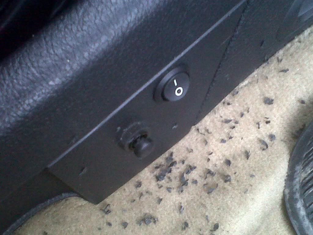
(ignore the second push button a mistake i made once)
So at the back of a standard SPST switch there is 2 terminals, and as you know when the switch is at I they are both connected, so now get another bit of wire, put the crimp connectors on to connect it to the switch and thread it up under the gear change gatier, under the ash tray, under the radio, into the passenger footwell, again using cable ties to keep it tight. At this point if you want you can just use the switch to manually turn on and off the power supply going to the footwell lights but where is the excitment in that, and they are not as useful then. Before getting the right circuit i had this setup for a while and its not really very useful.
Also its worth noting that it would be a good time to add a DPDT (Double pole double throw) switch now if you wanted instead of the SPST this would mean that you could have the footwell lights in 3 modes
- permantly off
- on
- on in tandem with the courtesy light
A DPDT switch really then only has the advantage of still letting you turn on the footwell lights independantly of the courtesy light, i didnt see it necessary as you can simply turn on the courtesy light as normal to activate the footwell lights when the circuit is finished, but its worth noting this now.
Now then the last external thing the circuit needs is an LDR, a Light dependant resistor, solder its legs onto a long strand of wire, colours dont really matter as LDRs dont have a politary. Anyway the wires need to be long enough to get from the overhead courtesy light down into the footwell, that means going past the sun visors, down the a pillar down through the dash (threading it down is easy just open that flap at the side of the dash and its a doddle) so cut the right length of wire.
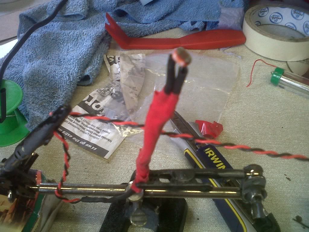
So here is an LDR soldered to the wires, make sure both wires dont touch or the thing would short and not work:
this is now a good time to connect a resistance meter, and check how the resistance of the LDR changes in the light and dark, its nice to see, but also confirms you didnt wreck the LDR when soldering it:
now then pull out the courtesy light, fully take it out of the car and into a shed or workplace, take the PCB bit of it off the plastic bit, the middle light is the one that we are after it gets turned on when the doors open, unlock, lock or when the key is removed for the igniton ie the perfect times for the footwell lights to come on, so putting the LDR therefore beside it is the perfect place. Mount the LDR about 3mm back off the hole for the bulb, on the plastic side, put a dab of adhesive on behind the bit that senses the light. Then put the PCB on again, make sure the LDR is sitting on its side or else the PCB wont go back on, screw the PCB back on and it will clamp the LDR in there very good. This shows what ive just described:
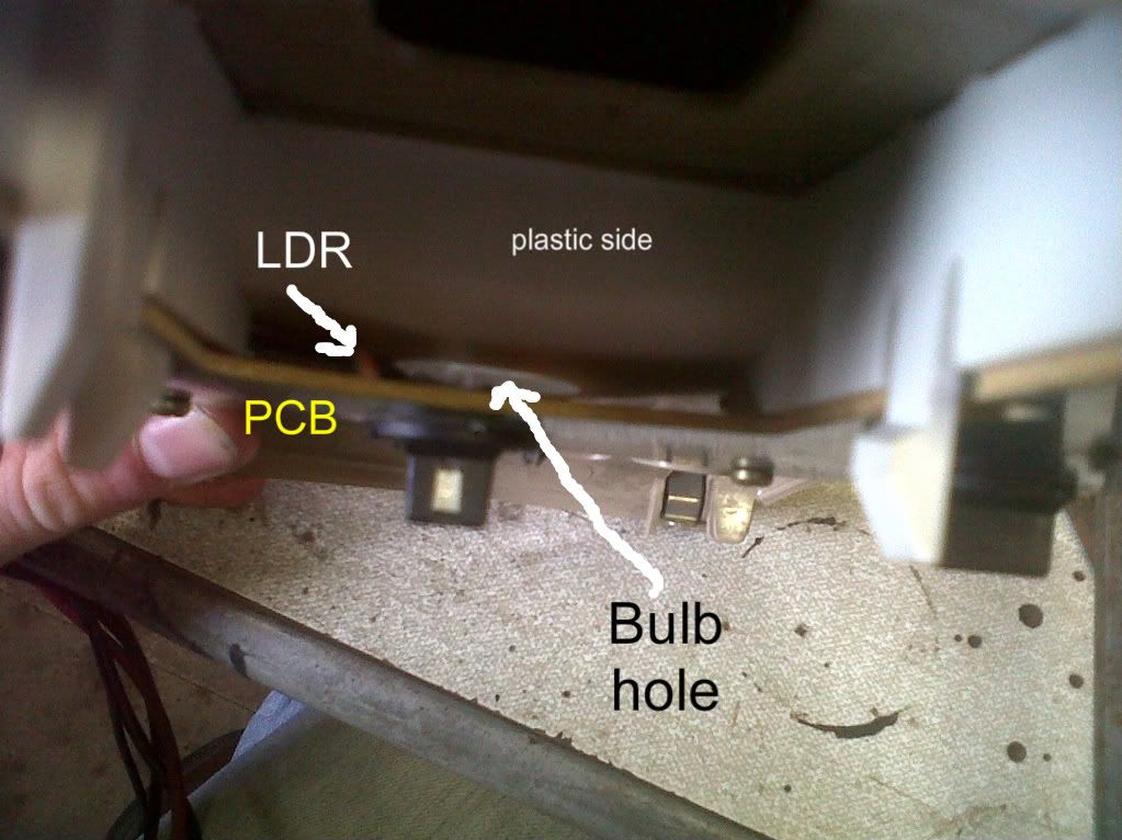
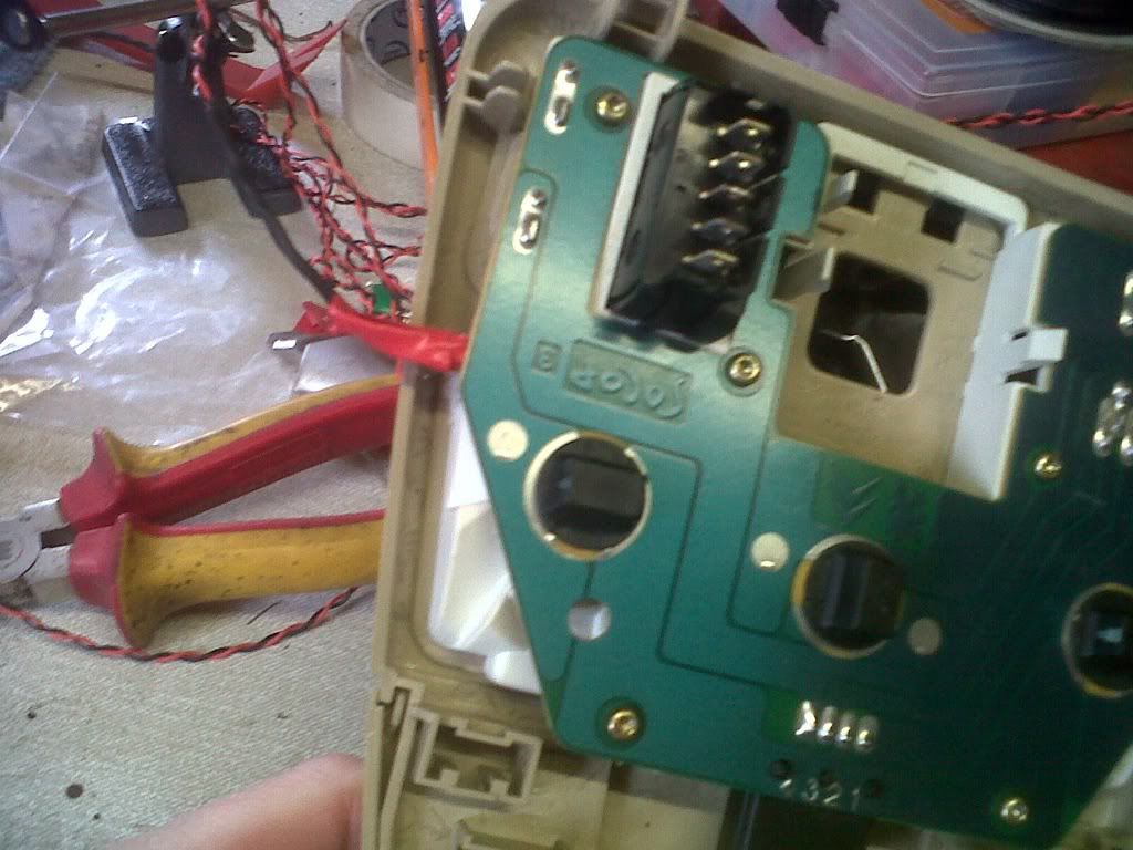
this is the back of the courtesy light showing the screws that hold the PCB into place.
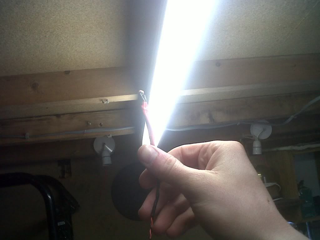
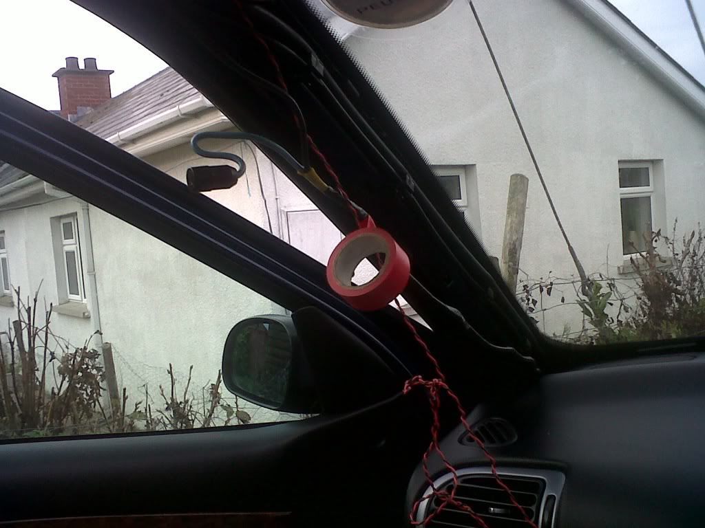
Thread the wire as described down into the footwell, this requires taking off the sun visor, and the A pillar, again make sure the wire is kept tight to stop rattles:
now confirm the LDR is working correctly, test the resistance with the light on:
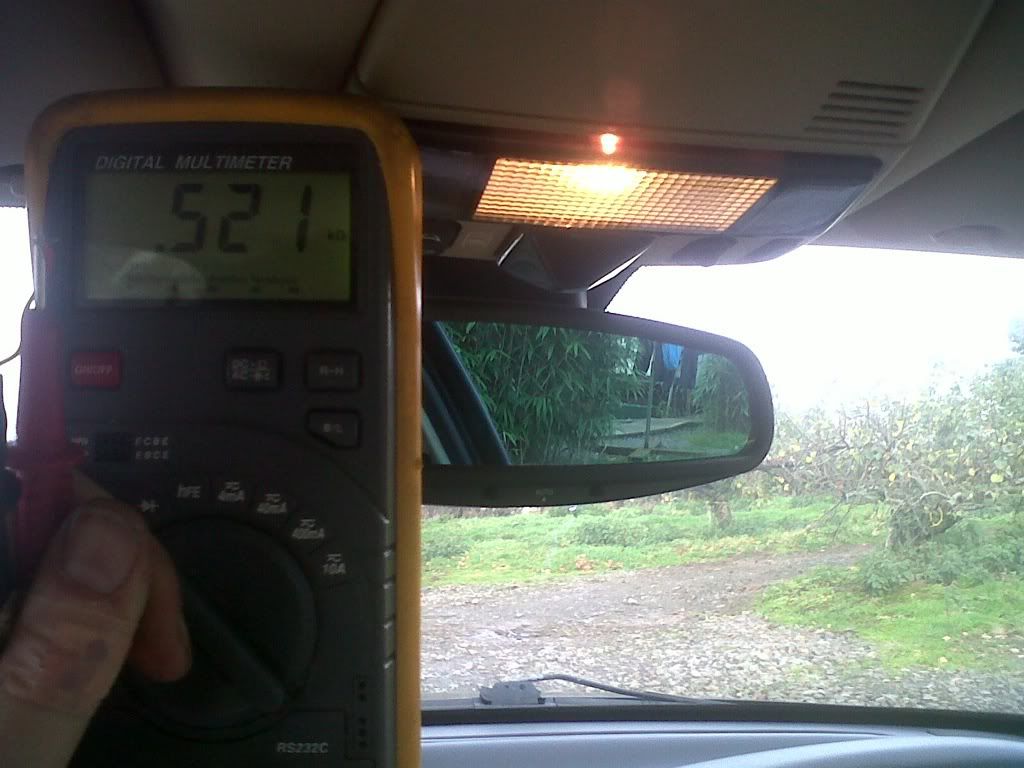
and off:
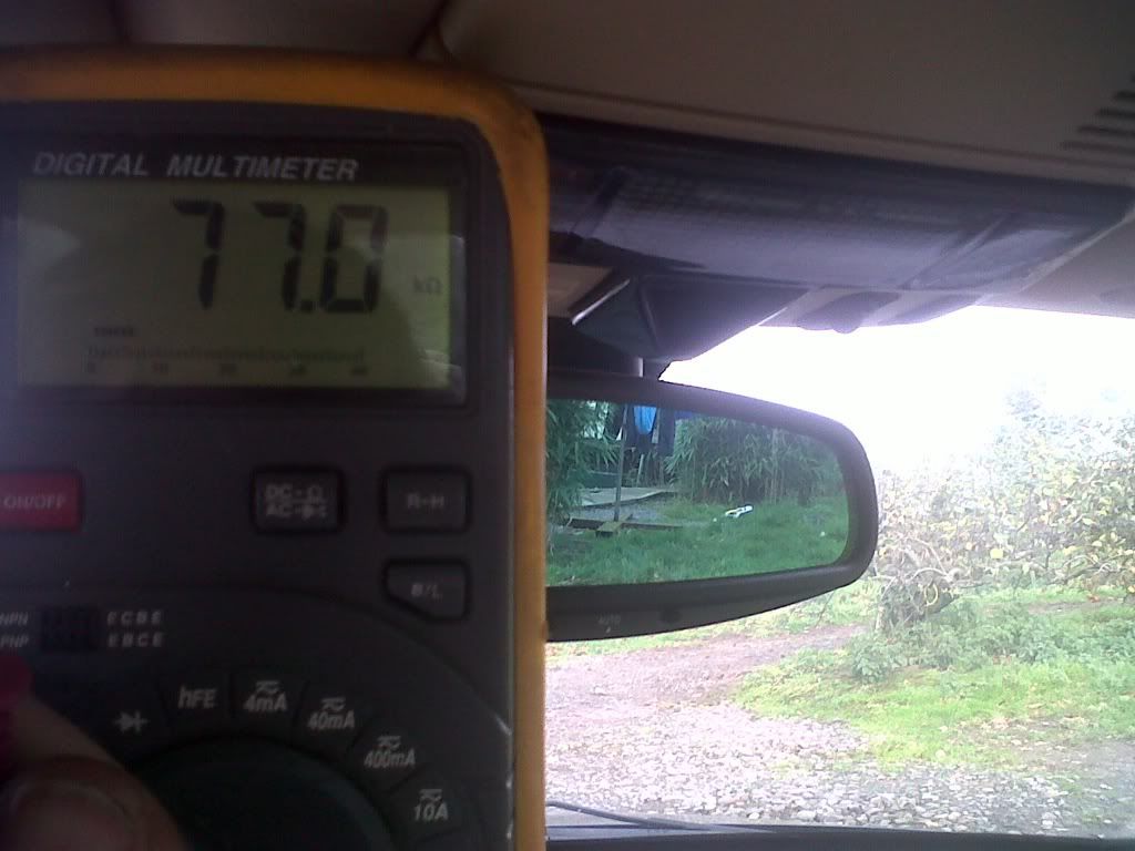
an analogue resistance meter would illustrate it better but basically the resistance should be significantly lower with the light on than off, dont worry about ambient light leaking in, the courtesy light lens takes care of that, and if you mount the LDR back about 3mm it will stop it getting affected by backround light, even better the circuit which will be used can have its switch on level adjusted.
Now then you need to purchase the Light activated relay circuit to take the 12v from the battery and switch it on sending power to the footwell lights when the courtesy light comes on. I tried designing my own circuit and building it wasted £30 trying to get the components to find out it didnt work, i also bought a dusk activated device £20 pissed down the drain, which was too insensitive and slow to react, i then got the right circuit but buggered up the soldering £10 lost, so the circuit to get is this one in the already assembled form:
http://www.quasarelectronics.com/3079a- ... switch.htm
Wait for it to arrive, then wire it up, wiring it is very simple it needs a power supply obviously, put the negative straight into it, and put one wire from the switch you mounted to the centre console to the +ve, and the other wire from the switch going to the positive, on this circuit. Which gives the switch the switching power over the positive supply.
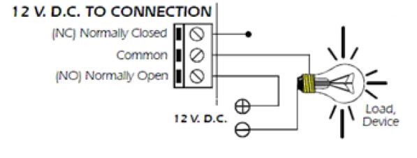
Then you need to think about how the footwell lights are to be wired up. Well they need to be switched, and its best to switch the positive supply, so wire up the negative supply directly to the negative, the same one used to feed the circuit, as for the positive, take the same positive supplying the circuit, and put it to the COM pin on the relay, then send the wire going to the positive of the footwell lights to the other pin of the relay. Ie like this diagram i got from the instructions:
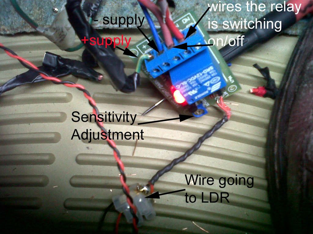
overall it should look something like this:
the LDR on a pre assembled circuit may be already mounted, you could snip it off, and solder the wires to its original legs (would also require heat shrink, and some form of insulation tape).
Alternativley unsolder the LDR, and solder in the wires from the courtesy light LDR straight onto the PCB, but that can cause damage to the copper tracks and ruin the circuit, if your not careful, so its your choice.
And hopefully that should be it, tuck it away in any manner you like, between the right left hand side of the car, and fan motor there is ample room to mount it somewhere, make sure wherever its mounted its mounted tight or you will hear rattles, and cover the circuit in some way, be it insulating tape or a neat plastic box, because it could touch something metal or another wire in the car and cause a fire. As could any badly done bit of wiring, so make sure all the connections you do are very good, and well insulated, so probably doing it proper and getting a pcb mounting box like this is the better plan:
http://cgi.ebay.co.uk/Project-Box-Matri ... _990wt_907
or
http://cgi.ebay.co.uk/ws/eBayISAPI.dll? ... 500wt_1156
You can make adjustments to the circuit to adjust the sensitivity so it only turns on when the light is on, but make sure the switch on the circuit is set to light activation otherwise it mean the relay is constantly powered up if the light is off (which in a car is off the majority of the time) which could drain the battery, the courtesy light for the majority of the time is off so it makes sense for the relay also to be off.
And thats how to install footwell lights, ive wasted quite a bit of money on trying to make the circuit myself and the wrong circuits, so these instructions are refined so that wastage doesn't have to be done. Of course if your not confident around car electrics dont try this, and remember im not an automotive or household electrician do this at your own risk, but its definitely much safter than nabbing a wire from the doorcard puddle lights and drawing power from them. This has recently been installed and i have had no problems, but will report back in a week on whether its causing any problems but i doubt it, because the whole point of this circuit is to be optically isolated from the BSI controlled courtesy light, in doing that it eliminates any chance of overloading the BSI or the electrical system. Anyhow hope this helps, and remember when working round the electrical system of your car be careful, if you dont know what your doing dont do it.
Right, now after all the time spent on getting these footwell lights, im very happy that they are now working so now from my experience (ie almost wrecking the BSI, trying 4 different circuits as a solution, and burning my hand a number of times with a soldering iron) i can now make a followable guide on how you can install footwell lights without causing any trouble to your BSI. But this isnt just for D9 multiplex owners, if you D8 owners have a similar thing and want to add footwell lights without drawing power from whatever the equivilant of the BSI is then this is the guide.
So to begin then, do the easy part, buy a pair of them peugeot square courtesy lights off ebay, you know the ones that old 205s had as a courtesy light, they will do best, but i had an old merc one and one from the boot of a 206 it doesnt matter too much what they look like unless your an acrobat and sit with your head in the footwell and legs on the chair, in which case i must say try the other way its comfier, a scrappies is the best place to look and see the best courtesy light for the job..
anyhow get the carpet topping of the footwells out, cut a hole for the lights, and slot the light in, tuck the material in carefully and tightly round the light and use glue just to get it in right and this is what it looks like when finished:
Now each light has 2 wires (as you would expect), because its a bulb there isnt any issue with politary, light will still come out. All the wiring for the footwell lighting gubbins is best done in the passenger side of the car because there is more room (well there is at least in cars with the steering on the right side) you dont want a load of wires under the drivers side as theres enough there already, as well as the pedals and steering. Anyhow you need to connect 2 core (+ve and -ve wire available from any hardware shop in a roll) cable from the drivers side footwell light, to the passenger footwell, this is very easy, it just threads behind the dash (threading doesnt need any of the dash to be pulled apart its easy enough), use plenty of cable ties to clamp the wire tight, and keep rattles away, make sure there is more than plenty of wire over at the passenger side, ie it should be able to reach the door.
With the drivers footwell open its a good time to bring the 12v power supply into the car, the 12v power supply has to come from the battery through the bulkhead into the passenger footwell. Of course some will know of other ways of getting a constant 12v feed, but this way worked, the bulkhead in front of the driver has a big collection of wires coming into the cabin, you can see the big thing below the scuttle, push a screwdriver through this, and twist it about until eventually the wire can go throught, this isnt easy bit it is possible, again get the wire into the passenger footwell, use cable ties and always make sure no wires obstruct the movement of the pedals. Once 12v is available at the passenger footwell you can put the drivers side footwell cover back up.
So you now have 12v into the car, you now need to put 2 wires onto the passenger side light, strip the wire back, for this one and the wire coming from the light at the drivers side footwell, take the 2 brown or red wires (whatever is inside the 2 core stuff) and put the two into the bottom of a terminal block, do the same with the blue/black wire, then on the other side of the terminal block bring out a single red and black wire from each hole, there you go the 2 footwell lights are wired together in paralell, if you give them 12v they should turn on, try it to see they work, as now is a good time.
At this stage you need a switch, because at some point you may not wish to have footwell lights turned on, so mount it somewhere your happy with, i mouted my SPST (single pole single throw) rocker switch into the side of the centre console, hidden by the seat when in my position, this one takes a 21mm hole:
(ignore the second push button a mistake i made once)
So at the back of a standard SPST switch there is 2 terminals, and as you know when the switch is at I they are both connected, so now get another bit of wire, put the crimp connectors on to connect it to the switch and thread it up under the gear change gatier, under the ash tray, under the radio, into the passenger footwell, again using cable ties to keep it tight. At this point if you want you can just use the switch to manually turn on and off the power supply going to the footwell lights but where is the excitment in that, and they are not as useful then. Before getting the right circuit i had this setup for a while and its not really very useful.
Also its worth noting that it would be a good time to add a DPDT (Double pole double throw) switch now if you wanted instead of the SPST this would mean that you could have the footwell lights in 3 modes
- permantly off
- on
- on in tandem with the courtesy light
A DPDT switch really then only has the advantage of still letting you turn on the footwell lights independantly of the courtesy light, i didnt see it necessary as you can simply turn on the courtesy light as normal to activate the footwell lights when the circuit is finished, but its worth noting this now.
Now then the last external thing the circuit needs is an LDR, a Light dependant resistor, solder its legs onto a long strand of wire, colours dont really matter as LDRs dont have a politary. Anyway the wires need to be long enough to get from the overhead courtesy light down into the footwell, that means going past the sun visors, down the a pillar down through the dash (threading it down is easy just open that flap at the side of the dash and its a doddle) so cut the right length of wire.
So here is an LDR soldered to the wires, make sure both wires dont touch or the thing would short and not work:
this is now a good time to connect a resistance meter, and check how the resistance of the LDR changes in the light and dark, its nice to see, but also confirms you didnt wreck the LDR when soldering it:
now then pull out the courtesy light, fully take it out of the car and into a shed or workplace, take the PCB bit of it off the plastic bit, the middle light is the one that we are after it gets turned on when the doors open, unlock, lock or when the key is removed for the igniton ie the perfect times for the footwell lights to come on, so putting the LDR therefore beside it is the perfect place. Mount the LDR about 3mm back off the hole for the bulb, on the plastic side, put a dab of adhesive on behind the bit that senses the light. Then put the PCB on again, make sure the LDR is sitting on its side or else the PCB wont go back on, screw the PCB back on and it will clamp the LDR in there very good. This shows what ive just described:
this is the back of the courtesy light showing the screws that hold the PCB into place.
Thread the wire as described down into the footwell, this requires taking off the sun visor, and the A pillar, again make sure the wire is kept tight to stop rattles:
now confirm the LDR is working correctly, test the resistance with the light on:
and off:
an analogue resistance meter would illustrate it better but basically the resistance should be significantly lower with the light on than off, dont worry about ambient light leaking in, the courtesy light lens takes care of that, and if you mount the LDR back about 3mm it will stop it getting affected by backround light, even better the circuit which will be used can have its switch on level adjusted.
Now then you need to purchase the Light activated relay circuit to take the 12v from the battery and switch it on sending power to the footwell lights when the courtesy light comes on. I tried designing my own circuit and building it wasted £30 trying to get the components to find out it didnt work, i also bought a dusk activated device £20 pissed down the drain, which was too insensitive and slow to react, i then got the right circuit but buggered up the soldering £10 lost, so the circuit to get is this one in the already assembled form:
http://www.quasarelectronics.com/3079a- ... switch.htm
Wait for it to arrive, then wire it up, wiring it is very simple it needs a power supply obviously, put the negative straight into it, and put one wire from the switch you mounted to the centre console to the +ve, and the other wire from the switch going to the positive, on this circuit. Which gives the switch the switching power over the positive supply.
Then you need to think about how the footwell lights are to be wired up. Well they need to be switched, and its best to switch the positive supply, so wire up the negative supply directly to the negative, the same one used to feed the circuit, as for the positive, take the same positive supplying the circuit, and put it to the COM pin on the relay, then send the wire going to the positive of the footwell lights to the other pin of the relay. Ie like this diagram i got from the instructions:
overall it should look something like this:
the LDR on a pre assembled circuit may be already mounted, you could snip it off, and solder the wires to its original legs (would also require heat shrink, and some form of insulation tape).
Alternativley unsolder the LDR, and solder in the wires from the courtesy light LDR straight onto the PCB, but that can cause damage to the copper tracks and ruin the circuit, if your not careful, so its your choice.
And hopefully that should be it, tuck it away in any manner you like, between the right left hand side of the car, and fan motor there is ample room to mount it somewhere, make sure wherever its mounted its mounted tight or you will hear rattles, and cover the circuit in some way, be it insulating tape or a neat plastic box, because it could touch something metal or another wire in the car and cause a fire. As could any badly done bit of wiring, so make sure all the connections you do are very good, and well insulated, so probably doing it proper and getting a pcb mounting box like this is the better plan:
http://cgi.ebay.co.uk/Project-Box-Matri ... _990wt_907
or
http://cgi.ebay.co.uk/ws/eBayISAPI.dll? ... 500wt_1156
You can make adjustments to the circuit to adjust the sensitivity so it only turns on when the light is on, but make sure the switch on the circuit is set to light activation otherwise it mean the relay is constantly powered up if the light is off (which in a car is off the majority of the time) which could drain the battery, the courtesy light for the majority of the time is off so it makes sense for the relay also to be off.
And thats how to install footwell lights, ive wasted quite a bit of money on trying to make the circuit myself and the wrong circuits, so these instructions are refined so that wastage doesn't have to be done. Of course if your not confident around car electrics dont try this, and remember im not an automotive or household electrician do this at your own risk, but its definitely much safter than nabbing a wire from the doorcard puddle lights and drawing power from them. This has recently been installed and i have had no problems, but will report back in a week on whether its causing any problems but i doubt it, because the whole point of this circuit is to be optically isolated from the BSI controlled courtesy light, in doing that it eliminates any chance of overloading the BSI or the electrical system. Anyhow hope this helps, and remember when working round the electrical system of your car be careful, if you dont know what your doing dont do it.
-
DiscoPol
- Shiny New C5 2.2 Bi-turbo!
- Posts: 1682
- Joined: Thu Oct 29, 2009 4:54 pm
- Location: Milanowek Poland. http://milanowek.pl/
Re: Wiring up Footwell lights
Nice write up Farmer  ,
,
bit too much d1cking about for me but then i have a Disco and lights are the least of my worries
so how much did this little project cost you then? start to finish, wasted and non working prototypes included? im just being nosey like and i know you enjoy tinkering just as much as me, i just dont have the time anymore
Disco

Welly wrote:Well butter my arse!
-
FarmerPug
- 2.0 HDI 110
- Posts: 9656
- Joined: Tue Jun 01, 2010 5:42 pm
- Location: The Countryside, Northern Ireland
- Contact:
Re: Wiring up Footwell lights
about £80 wasted down the drain so thats why this writeup will stop anyone wasting any of their money, all the reasearch has been done for you.
if i got the chance i could do it all again for £20, id set aside a day, but really the process of getting all them things done was done over a number of months. But it is expandable, you can simply add more relays to turn on when the courtesy light comes on which would be handy for turning on door handle lights, mirror puddle lights, or whatever the imagination can think of as being useful, or nice.
if i got the chance i could do it all again for £20, id set aside a day, but really the process of getting all them things done was done over a number of months. But it is expandable, you can simply add more relays to turn on when the courtesy light comes on which would be handy for turning on door handle lights, mirror puddle lights, or whatever the imagination can think of as being useful, or nice.
-
Welly

- The moderator formally known as Welton
- Posts: 15033
- Joined: Tue Jan 10, 2006 12:52 pm
- Location: East Midlandfordshire
Re: Wiring up Footwell lights
What a write-up  you should be thanked for spending the time to do this, so, thanks
Watching the vid I like the way the lights turn off suddenly kinda like..."can you see ok? yep? right that's enough then"
Watching the vid I like the way the lights turn off suddenly kinda like..."can you see ok? yep? right that's enough then"
Cars in my care:
2021 Kia Spottage 1.6 Pez Turbo Dual Clutch Gearbox Trickery
2013 Renner Twingo - donkey work
2021 Kia Spottage 1.6 Pez Turbo Dual Clutch Gearbox Trickery
2013 Renner Twingo - donkey work
-
FarmerPug
- 2.0 HDI 110
- Posts: 9656
- Joined: Tue Jun 01, 2010 5:42 pm
- Location: The Countryside, Northern Ireland
- Contact:
Re: Wiring up Footwell lights
car brochure material there. It retains the delay of the courtesy light, but cant really do the slow dimming effect, its just a bit more decisive than the courtesy light, just yup thats enough light for now, im off.Welly wrote: Watching the vid I like the way the lights turn off suddenly kinda like..."can you see ok? yep? right that's enough then"
-
Hangar18

- 2.0 16v
- Posts: 178
- Joined: Tue Apr 19, 2011 10:24 pm
Re: Wiring up Footwell lights
Just a thought Farmer-
I've got a D8 tubby- what's to stop me taking that LDR activated circuit; and tapping the power cables for the courtesy light into the LDR's position-
So that instead of drilling a hole into the courtesy light- I'm using the power supplied to the light as a switch?
Or would that be difficult/impossible due to the difference between an LDR's resistivity and a power cables current?
1996 406 Executive XU10J2CTE
1995 405 GLX XU7JP
1995 405 GLX XU7JP
-
FarmerPug
- 2.0 HDI 110
- Posts: 9656
- Joined: Tue Jun 01, 2010 5:42 pm
- Location: The Countryside, Northern Ireland
- Contact:
Re: Wiring up Footwell lights
i didnt drill a hole in the courtesy light i mounted the circuit down in the footwell because the 12v feed was down in there and there was not the room for the circuit up by the courtesy light.
-
Hangar18
- 2.0 16v
- Posts: 178
- Joined: Tue Apr 19, 2011 10:24 pm
Re: Wiring up Footwell lights
IFarmerPug wrote:i didnt drill a hole in the courtesy light i mounted the circuit down in the footwell because the 12v feed was down in there and there was not the room for the circuit up by the courtesy light.
I understand that- what I meant was using a cable linked to the courtesy light instead of an ldr- so its current activated instead of ldr resistance activated?
1996 406 Executive XU10J2CTE
1995 405 GLX XU7JP
1995 405 GLX XU7JP
-
FarmerPug
- 2.0 HDI 110
- Posts: 9656
- Joined: Tue Jun 01, 2010 5:42 pm
- Location: The Countryside, Northern Ireland
- Contact:
Re: Wiring up Footwell lights
ah right cant do that in a d9 because it sends the bsi mad i dont know if a d8 has a bsi or not
-
wasp
- 2.0 16v
- Posts: 109
- Joined: Sun Feb 17, 2008 9:28 am
Re: Wiring up Footwell lights
I ,being a complete wildcard & chancer and without your electrical expertise,wired mine into the front roof interior light,did this 2 tears ago and the bsi is still alive n well .....atm! maybe cos its a preplexed system? lights dim out with the interior lights.
As your good with volts. maybe you could design and post a how to on power fold mirrors working of the deadlocking circuit?))
Dave
As your good with volts. maybe you could design and post a how to on power fold mirrors working of the deadlocking circuit?
Dave
"A HDI Is For Life and NOT Just For Xmas!!!"
-
FarmerPug
- 2.0 HDI 110
- Posts: 9656
- Joined: Tue Jun 01, 2010 5:42 pm
- Location: The Countryside, Northern Ireland
- Contact:
Re: Wiring up Footwell lights
i would normally just wire them straight to the courtesy lights but after the puddle lights went all go mad i decided not to do that. I think it may be possible to get away with leds but as it says in the manual any more than 10ma and it should be done by the dealer, thats why i went for an opto isolator, so i could draw as much current as i wanted without any worries.
As it is the circuit turns on the footwell lights in the front, but i plan to put a pair under the front seats, make it easier to make your way into the back.
as for the folding mirrors, im not that good to know how to wire them up, its a good idea though for them to come on with the deadlocks, the idea of them folding when the ignition is off isnt good because if you park your car on the side of the road and try to get out you need the mirrors to see if you can open the doors.